This is an old revision of the document!
Replacing the heat bed connector
- article under development, please add your knowlage and feel free to edit - The corresponding discussion can be found here
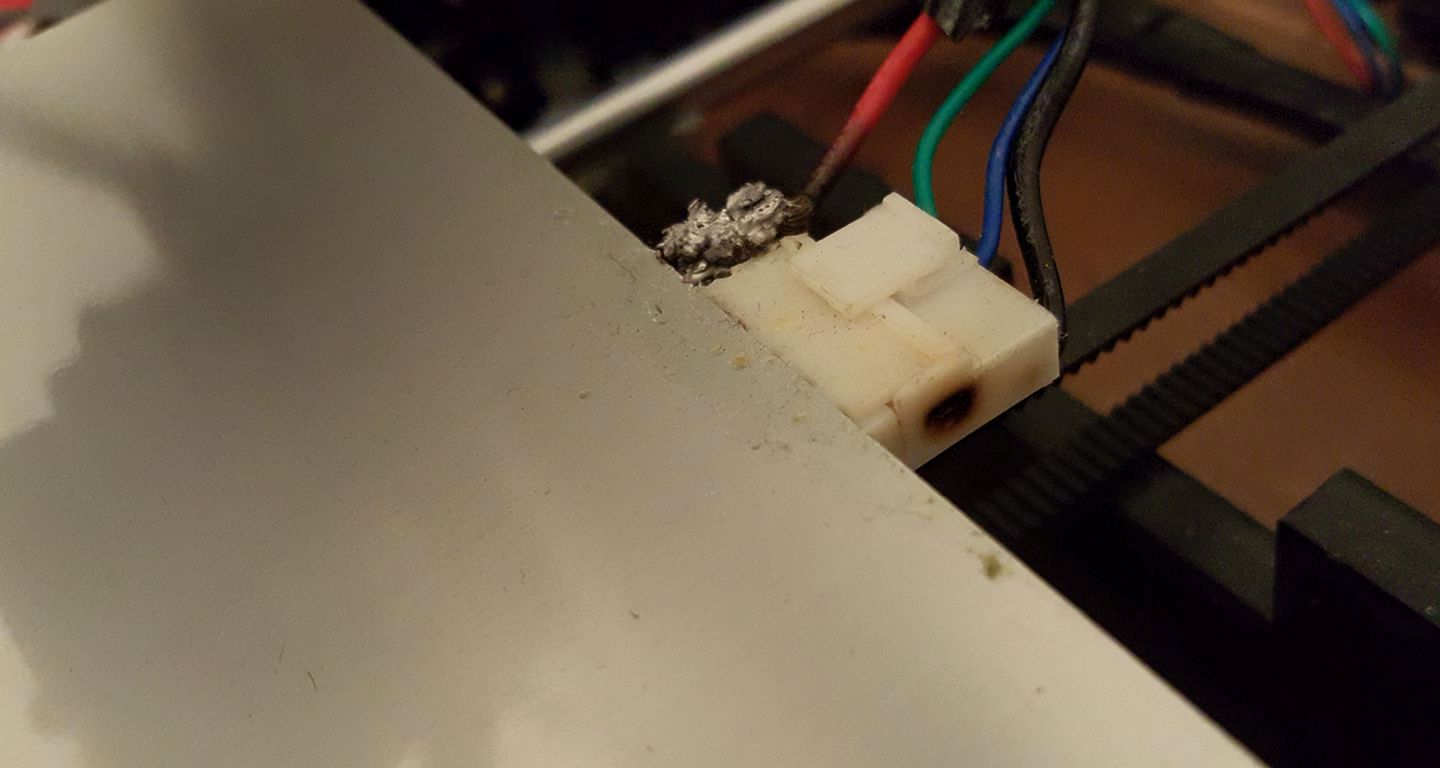
A very common issue are scorched heat bed connectors like this:
Root cause
There are several opinions about the root cause of this problem. Which is the main root cause or if it is a combination of them is still to be discussed. Here some collected facts and arguments.
The connector is a VHR-6N from JST rated to 10A. The heat bed draws around 10A at room temperature and less when hotter (click here for details). So theoretically the connector is just enough. But these connectors are not designed to constantly moving aroud so a strain relief(see below) could probably solve the problem.
 NOTE
 Always keep in mind:
 Wherever there is an electric current flowing through a circuit. there will be heat developing whenever it encounters a resistance.
 The hotbed heater has a small resistance ( between 1 and 3 Ohm) and it is designed to develope heat and it can sustain the heat.
 A large resistance in the connector will limit the current a lot and it will prohibit any real heat developing in the heater.
 A small resistance in the connector (lets asume just 1 Ohm) will limit the current just a very small amount and a lot of heat will
 develope in the connector almost equal to that of the heater intself.

 ERGO a meltdown of the connector is in progress
Other possible reason for failures could be:
- poor quaity of the crimps
- stiff stock wires or wrong size
- that only 1 of the two + pins and one of the two - pins are used instead of both + pins and - pins reducing the current for each.
How to repair
There are several options to repair scorched connectors
Option 1 - Replace the connectors with the same type
You will need:
- 1x VHR-6N from JST
- 4x SVH with AWG 16 pre crimped pigtails like these or
- 4x SVH-41T-P1.1 pins
- crimping tool
- pliers and side cutters
- Silicone wires with thins strads AWG 16 to 18.
The heat bed connector has 4 pins for + and -. The + pins can be used in paralell, the - pins also. This reduces the current on the pins and therefore the probability of failure.
It is recomended to add strain relief.
Option 2 - Solder
Soldering cables directly onto the heat bed is a very reliable option if it is well done. But soldering thick wires onto a heatbed with a large thermal capacity is quite dificult and requires some soldering experince to avoid cold joints. As this connection has to withstand a quite high current and a failure may lead to fire, this not recomended for a first time soldering experience.
Recommendations: * Use a solderingiron of good capacity (75/100 Watts). A smaller iron will not melt the solder enough to get a good electrical
 connection (the more metal you need to heatup for a joint the more capacity you need, keep heating it with a low capacity iron for
 longer time is not good)
* Do not OVERheat the solderjoint. As soon as the solder melts on both the wire and the pad keep the wire motionless till the solder has
hardened (if it moves while hardening the joint will be no good eventhough the wire might be "stuck on")
* Preheat the heatbed before soldering in a oven or by its own heater. * The solder on the heat bed is probably lead free solder. Most people use leaded solder at home. As mixing them is not recommended it
is better to remove as much old solder as possible before soldering.
* Foresee a strain relief so that the constant bending of the wire does not stress the solder
Option 3 - spade connectors
-feel free to write this chapter -
Option 4 - european style screw connectors
-feel free to write this chapter -
Strain relief
A strain relief reduces the stress on the connector/solder. This is a good idea independently of which option was chosen or as a preventive measure before it fails. Here some options:
- 90° angle connector https://www.thingiverse.com/thing:17916
 NOTE
 a cablechain was mentioned above: For cablemanagement it might look nice but there are some drawbacks on this.
 It will bend the complete wire 180 degrees over the whole length of the wire with every motion.
 In my opinion a better way is to keep the bending as gradual as possible spread out over the complete length of the wire.

 To clarify: let the hotbedwire(s) run from the top of the printer to the bed. the motion of the bed will then never bend the wires more
 then maybe 15 degrees spread out over ca 30 cm. therefore hardly any bending at all in a specific place.
Remarks:
- By replacing the stock wires by thicker ones (AWG 14 or 16) you can increase the heater power (explanation). For the JST crimp connectors AWG 16 is the thickest wire compatible with the SVH-41T-P1-1 pins
- The connector at the HB is: B6P-VH(LF)(SN)
Comments
Also it is prefered to discuss the content in the discussion link (see top) you can add comments here: