Howto Connect your Hotbed (and or extruder) to a Mosfet
WARNING
I have seen people trying to (re-)sell these MOSFET units with a HUGE profit on eBay while referring to this page for installation schematics. Go shop around — they don't need to be more expensive than around €5 to €10 ($5 to $10) incl. PP.
Click here for an example of some prices
Why
The idea is pretty simple: the high current of the hotbed brings multiple problems to your mainboard.
All the current for the bed has to go through the one connector in addition to all the other current for the hotend, the steppers and the logic units. The default connectors are not rated for the current that goes through them when printing. Things like in the picture below happen to almost every printer at one time in its life.....
 connector and corresponding plug
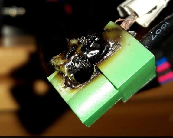
EDIT: the latest version of the control board has newer/different type connectors fitted — they are safer, but if not connected properly even they CAN and WILL melt. Remember: transition resistance in combination with high(er) currents equals heat development.
Removing the hotbed current from the mainboard significantly reduces stress on your mainboard (connectors).
Another benefit: it will allow you to use a second PSU for bed power (12 or 24 volts).
What you need
- A MOSFET unit like this, a 2-pin JST connector with some wire, and some thicker wire(s) AWG 16 or AWG 14 (1.5 mm² or 2.5 mm²)
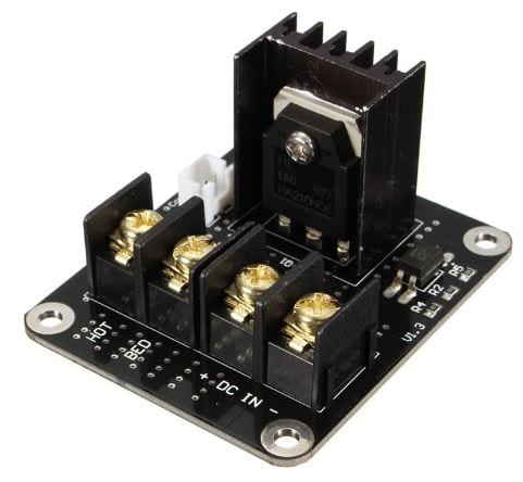
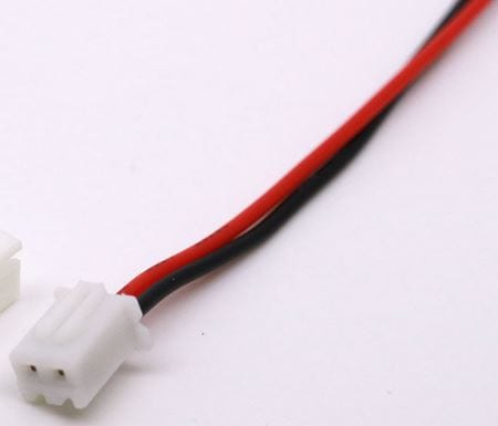
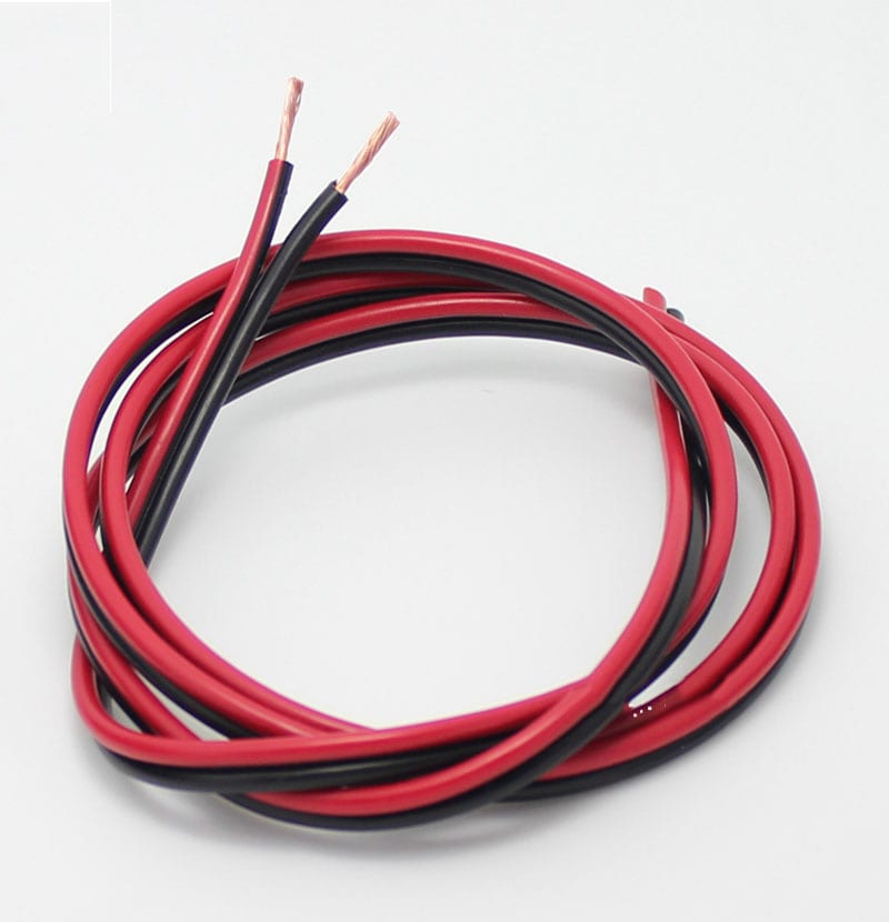
Note: Some MOSFETs are sold with the signal wire, some without. Check if you need to buy a separate one.
3D Printer Parts General Add-on Heated Bed Power Expansion Module — on banggood.com
Question: Can I use a mechanical relay too?
Answer: Theoretically... yes, but mechanical switches are generally not meant for the large number of repeated on/off cycles that your printer will generate.
How to install
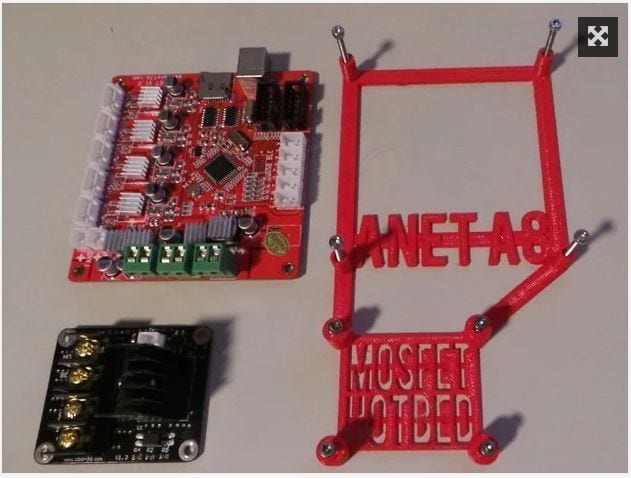
A special bracket to mount your ANET mainboard and 1 MOSFET unit you can find here: https://www.thingiverse.com/thing:1857006
NOTE: More than one version of the ANET control board is being shipped from China (with and without version numbers). Always check for + and − (polarity) on the boards.
- RED = + (on PSU marked as +V)
- BLACK = − (on PSU marked as −V or COM)
NOTE: I used an easy way to wire this using the stock 12 volts wire and without cutting it, just removing about 1 cm of the insulation (to connect the MOSFET board), ran it from PSU to MOSFET board to control board (applies if you use 1 PSU only). Other people might want to use 2 sets of wires, 1 for the control board and the extra set of wires from PSU to MOSFET board.
- Unplug your printer's power cord
- Remove the power cables of the heated bed from the mainboard and attach them to the power output of the MOSFET unit
- Connect 2 wires from the bed output of the mainboard to the control input of the MOSFET (polarity DOES NOT MATTER for this signal wire)
- Connect 2 wires from the PSU (either the same as the printer, or a second PSU) to the power input of the MOSFET unit (here polarity DOES MATTER)
- Check twice against the graphic
For the signal wire there has been some confusion
Some people claim polarity matters — they are right sometimes, some MOSFETs are polarity sensitive.
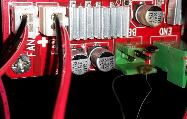
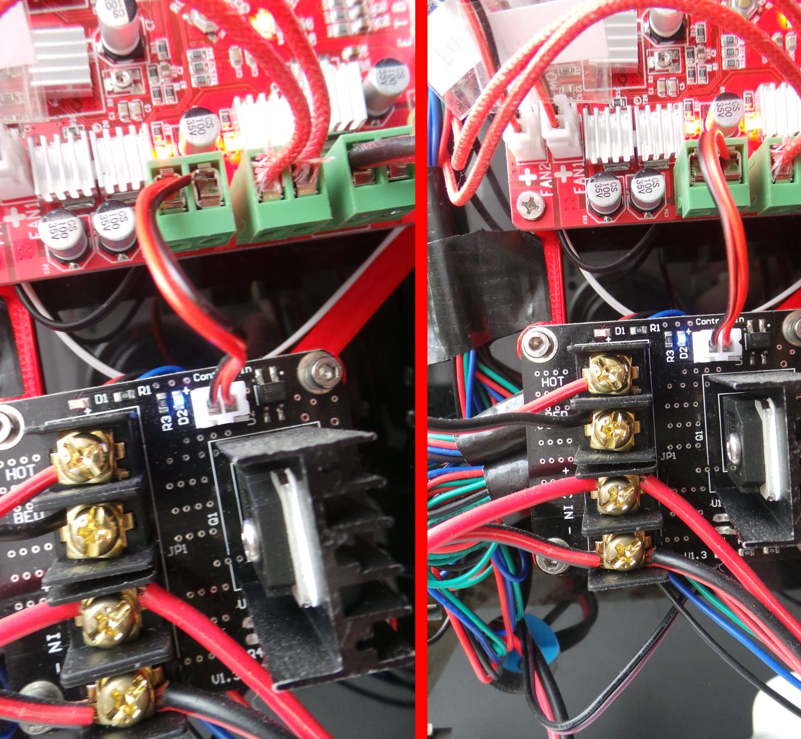
For the MOSFET unit shown in the 2 pictures here, POLARITY DOES NOT MATTER. Check them side by side with the signal wire connected both ways.
In both pictures the hotbed was set to preheat PLA; both LEDs, blue (D2) and red (D1), light up and everything functions as it should. In the photos below you can see the "bridge rectifier" on the MOSFET (just to the right of the white plug) which corrects "wrong" connection of this wire!
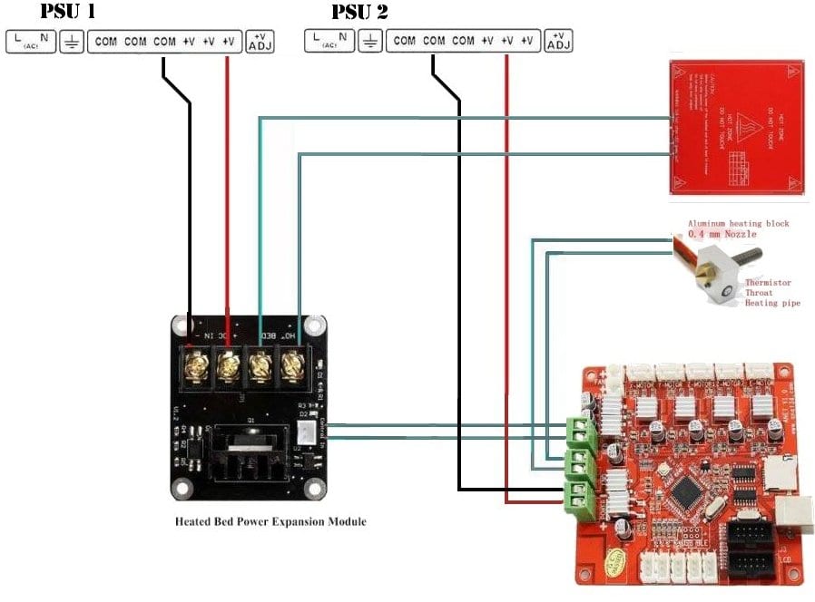
Apply a second PSU (12 or 24 volts)
If you want your HOTBED to heat up faster you can add a second power supply unit to your printer.
Disconnect the wires from the PSU to the MOSFET unit and apply them to the second PSU.
The heating element that came with the Anet A8 will perform OK with an increase of the (PSU 1) voltage to 14 Volts. This will help the bed heat up significantly faster.
Apply a second Mosfet (for the extruder)
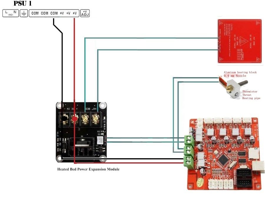
Even though in my opinion it is not really necessary, you might decide you want to use a 2nd MOSFET for your extruder as well. Here is a schematic you might find useful:
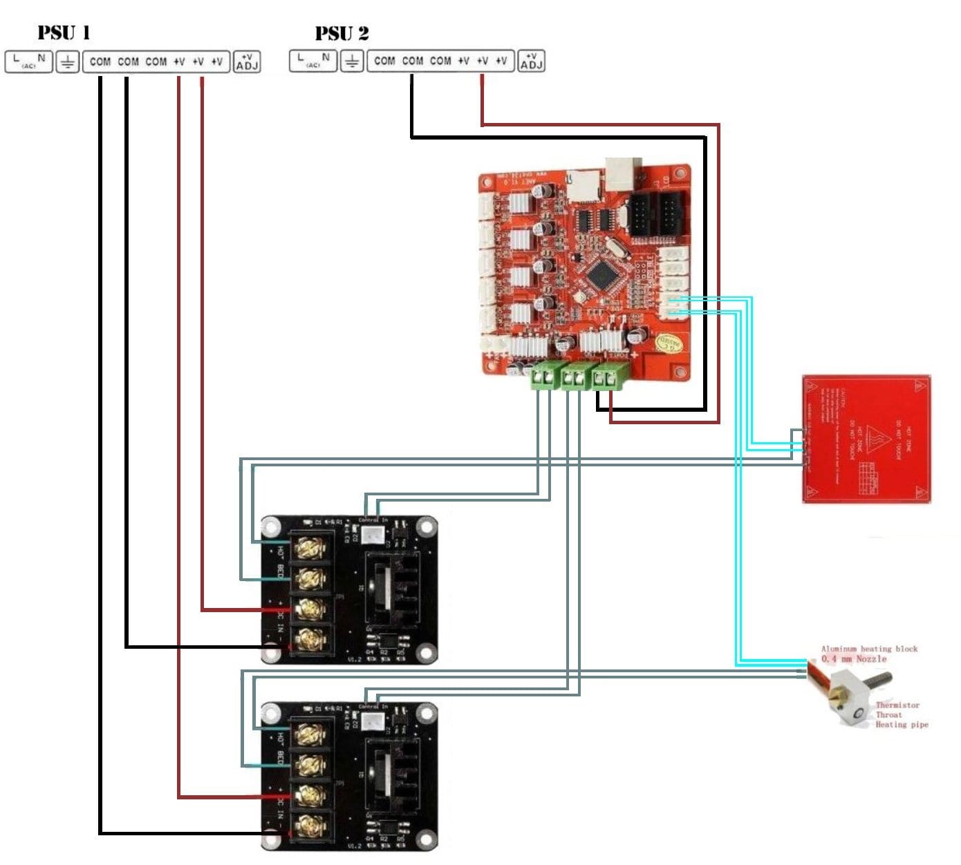
Of course you can use 1 (upgraded) PSU for all the 12 volts wires if you choose to.
Note: ( RED = + ), ( BLACK = − ), ( GRAY = polarity does not matter ), ( TEAL = thermistor wires )
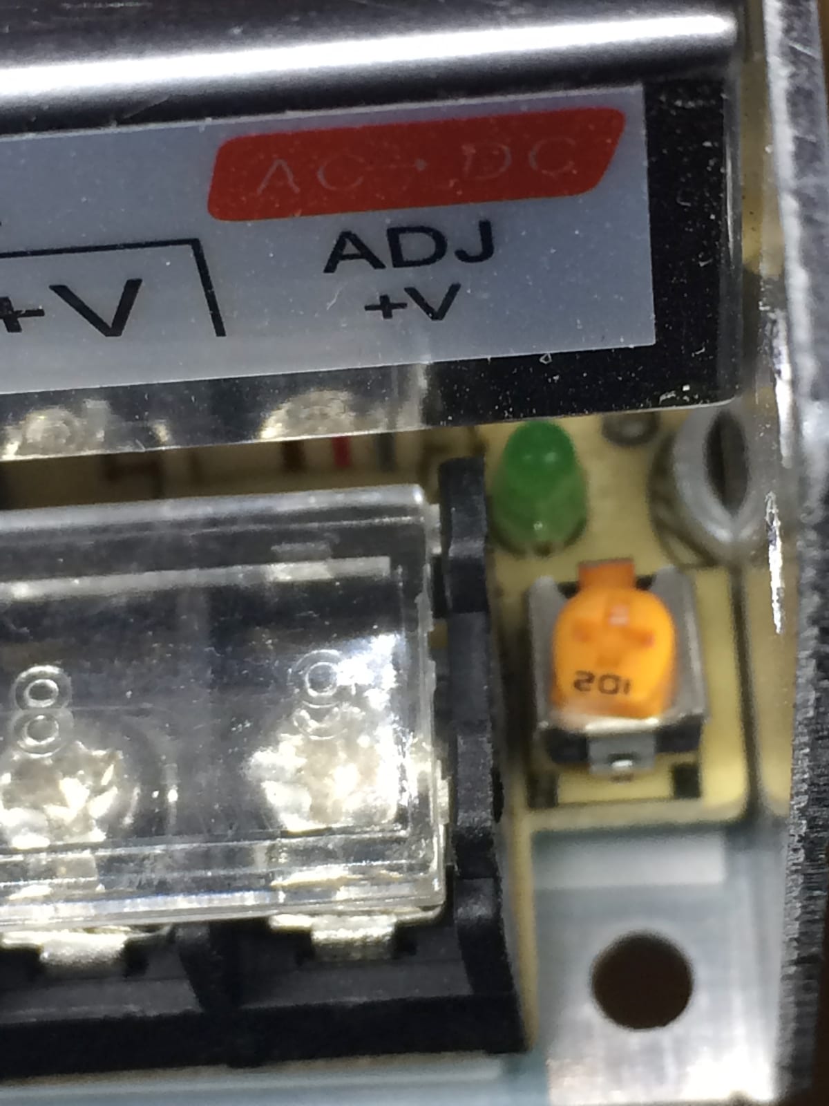
Increasing Voltage on the (stock) PSU
Note: This does NOT apply to an ATX PSU! You cannot change the voltage output on these, don't try.
Near the power terminals, either on the left or the right of the terminals, is a small dial marked "ADJ +V". Rotate it clockwise to increase voltage, and counter-clockwise to decrease it.
Always disconnect your power supply before making adjustments!
Check the voltage between one of the + and one of the − terminals, using a multimeter set for voltage DC.
PSU combinations
There are a lot of combinations possible.
1 × 12 volts PSU
NOTE: This is the standard setup.
2 × 12 volts PSU — of the one used for the heatbed you could raise the voltage to circa 14 volts.
NOTE: If you have an ATX power supply laying around, use the "stock PSU" for the hotbed and the ATX for the control board and stepper motors.
Since there are a million different ATX PSUs, I will give some "general" things for you to consider only — no specifics about ONE PSU.
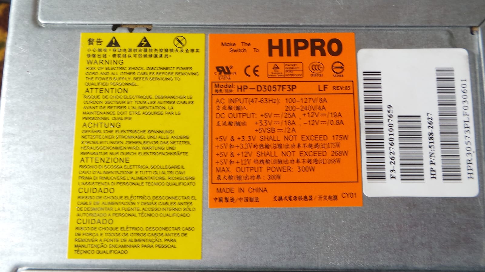
Check the ATX PSU you plan to use for a label like the orange one in the picture and check for maximum currents it can supply. Note that using multiple voltage outputs at the same time means less available current for the separate outputs than stated as maximum, sometimes.
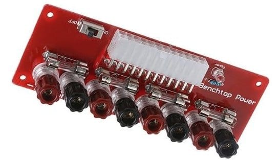
For easy connecting of your ATX power supply unit, you could use a breakout board like in the picture. Check your PSU for maximum power (Amps) and order some extra fuses to replace the stock 5 amp fuses that come with the unit, if you plan to draw higher currents through the breakout board.
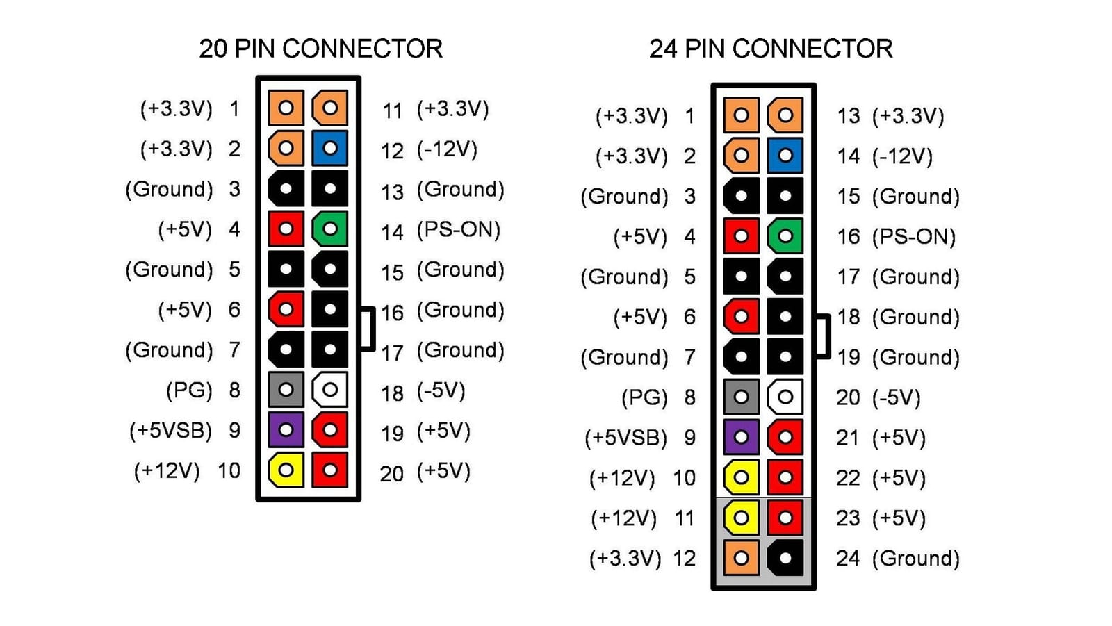
Another way is to just short the green (PS-ON) and black (GROUND) wire in the 20/24 connector to make the PSU be always ON, and use the wires from the wire loom as you need them. Just make sure the specific wires are designed to supply the current you need.
1 × 12 volts + 1 × 24 volts — the 12 volts one is used to power the mainboard, extruder and stepper motors; the 24 volts powers the heat bed (through the MOSFET).
NOTE: Make sure you use the 24 volts connections on the heater.
12 volts PSU + 24 volts PSU combination
The heating element in your HOTBED (as seen in the picture below) can be wired to support a 12 or 24 volts connection. The schematic printed on the surface shows pins 1, 2 and 3.
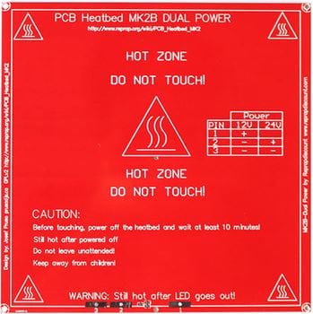 representation of the element
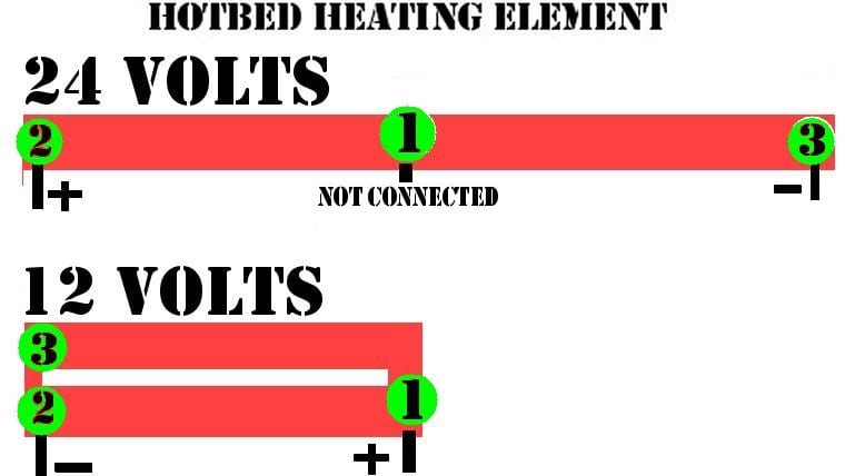
If wired for 12 volts, the element is doubled up, resulting in less resistance / higher current / slower heating and less power output.
If wired for 24 volts, the element is connected from both ends only, resulting in higher resistance / lower current / faster heating / higher power output.
NOTE: There is more than one model of heating element available on the market. Before you start any work, check which one you have and whether you can use the 24 volts option.
Do the math....
V = R × I (Voltage equals current multiplied by resistance), P = V × I (Power output equals voltage multiplied by current)
HOTBED 12 Volt connection — resistance between 1.0–1.2 Ω (work with 1.1 Ω)
- I = V/R → the current drawn at 12 Volts is 12 / 1.1 = 10.9 Ampere
- P = V×I → power output at 12 Volts is 12 × 10.9 = 130.9 Watts
HOTBED 14 Volts connection — resistance between 1.0–1.2 Ω (work with 1.1 Ω)
- I = V/R → the current drawn at 14 Volts is 14 / 1.1 = 12.7 Ampere
- P = V×I → power output at 14 Volts is 14 × 12.7 = 178.2 Watts
HOTBED 24 volts connection — resistance between 3–3.4 Ω (work with 3.2 Ω)
- I = V/R → the current drawn at 24 Volts is 24 / 3.2 = 7.5 Ampere
- P = V×I → power output at 24 Volts is 24 × 7.5 = 180.0 Watts