Table of Contents
Understanding the heat bed
This article documents the tests and analysis I have made to understand my Anet A8 printer heat bed (at work).
Summary & main conclusions
The Anet A8 heat bed is designed quite near its limit and small effects may prevent you from achieving temperatures above 100°C. Under ideal conditions, the heat-bed can just reach the temperature needed by ABS. To achieve higher temperatures a few changes are needed.
Here are the main recommendations for those who just want the results:
- Insulate against thermal conduction losses - thick insulation is needed to have a significant effect. Use as much insulation material as you can fit under your heat-bed.
- Insulate against thermal emission losses - a considerable amount of power is emitted as infrared radiation. This can be easily reduced by using aluminium foil as a cover layer on the bottom.
- Increase the voltage at the heat-bed:
- Thin wires create a significant voltage drop between the power supply and the board, and from the board to the heat-bed. Replace the wires by AWG 14 or AWG 16 silicone wires.
- You might increase the voltage of the power supply - but be careful not to overload the power supply.
- Use an enclosure - this increases the temperature by preventing losses via air convection.
If you what to simulate your heat bed, here is the simulator:warm_up_2.xlsx
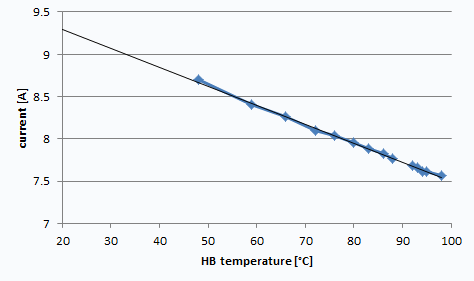
One interesting point is that the current decreases at higher temperatures due to the temperature dependency of the electrical resistance.
For those who what to know the details, here is the full report.
Introduction
My heat-bed could not reach temperatures above 102°C and normally skynetV2 already aborted at 92°C. I thought that if I could just insulate the heat-bed bottom I could easily reach higher temperatures. After applying some cork I was really disappointed by the result because it hardly changed anything. So I started analyzing how this can be. My results are here so everybody can use them.
How I tested
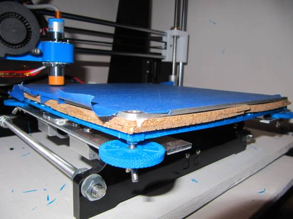
My printer is an Anet A8 without modifications on the board, power supply or wiring (initially). The Firmware was SkynetV2. I always tested inside a large plaster enclosure which was not fully enclosed. Unfortunately I couldn't measure the temperature inside but it was always between 18 and 28°C, based on sporadic measurements. The temperatures on the heat-bed were read from the display, which I recorded every minute. The beginning set-point for the heater was 115 (set via Gcode), the warm up procedure was always around 92°C (aborted by SknetV2) or set by manual control (No abort). The Insulation was two layers of 3mm cork sheets glued together. These were pressed against the heat-bed bottom by a blue ABS frame. The heater itself was still glued to the aluminium plate.
First test results
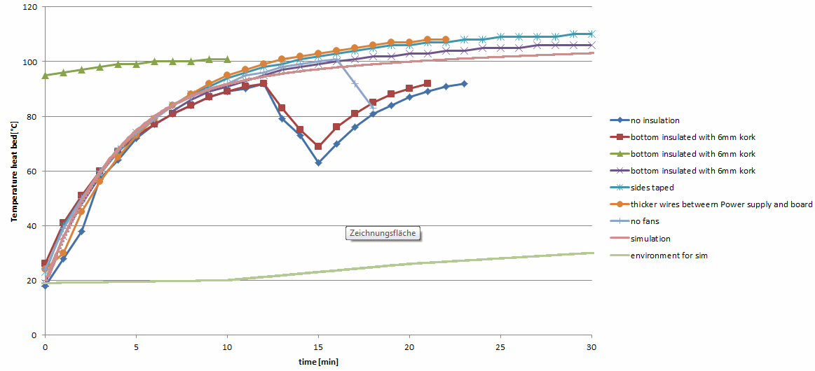
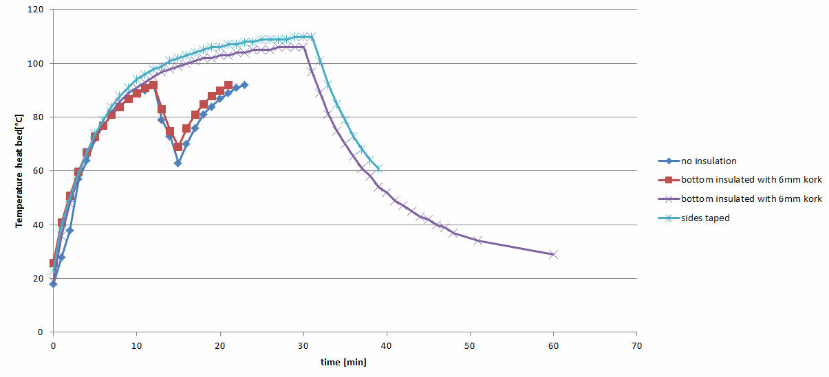
The first test was conducted without insulation on the heat-bed (there are some timing errors at the beginning of the red curve). Skynet3DV2 aborted the heating procedure (probably because it was not fast enough) by an error triggered at 92°C. I restarted the heating after some minutes.
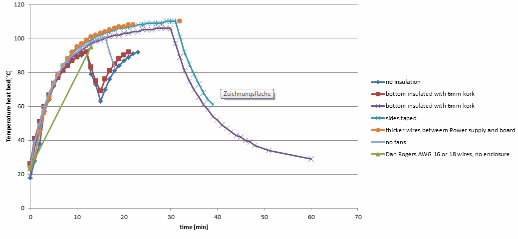
In order to see the maximum temperature reachable I had to set the bed temperature via control→ temperatures. The resulting green curve are those temperatures. It topped out at 102°C.
That the initial gradient is always the same is expected because the thermal capacity of the heat-bed (approx. 0.426kg * 890J/kgK=379J/K) and the power dissipated by the heater (approx. 105W) is the same and there are nearly no heat loses. The gradient fit the expected value of 110W / (379J/K) = 17.4K/min.
The curve flattens as the heat-loss increases, reaching a steady state when the amount of dissipated power equaled the heat lost to the environment. This equilibrium is explained later in detail. Basically with better insulation the later part is expected to be steeper and reach a higher final temperature.
My initial thought was that, if I added a little bit of insulation at the heat-bed bottom I could nearly eliminate half of the heat losses and easily increase the final temperature. Well, let's just say I learned something. It was very disappointing to see that the curves were nearly identical and no effect was visible. So I had to find out why my expectations were wrong and started investigating it in more detail.
Reproducing the test
I reproduced the test with several configurations. Apparently a small improvement was achieved by taping the sides - but it was nothing dramatic.
Investigating other effects
A good hint from a Facebook group member was to check the cables. There is a significant voltage drop from the power supply to the heat-bed. Note that the power dissipated at the heat bed is proportional to the square of the heat-bed voltage.
Replacing the power supply to heat-bed wires with thicker, shorter wires meant I could increase the power a little bit - doing that does not affect the heat-bed loss or contribute any insulating effect though. I also investigated if the loss was caused by forced convection from the extruder fans. I could achieve slight improvements, but nothing spectacular. Independently, Dan Rogers posted results for his heat-bed (only 2 points) - the results suggested my bed was operating similarly.
 .
.
Heat-bed Power
As the curves were very similar, I investigated if the effect was caused by the controller rather than being a thermodynamic effect (the controller adjusts the PWM duty cycle - and thus the curve). The voltage was a flat line on the oscilloscope, therefore this theory was discarded.
Then I measured the current and observed that it drops with increasing temperature.
Resistance is calculated by dividing voltage by current - this lead to the following resistance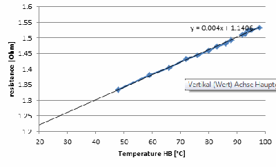
This gradient nearly fits the gradient expected for copper with an temperature coefficient of approximately 0.0039 1/K
This is probably the reason why there are values of 1.2 to 1.6 Ohms mentioned in some forums and sites for this heat-bed.
Simulating the heat bed
In order to understand the heat bed behavior in more detail I made a heat bed simulator in Excel (despite not liking this software for simulations). It fits quite well to the measured data, therefore it seems to be not so bad - but keep in mind that it is a model and not reality.
The cool thing about simulations is that you can evaluate heat fluxes which are difficult to measure and to make a series of variations which would require months of testing in a few minutes.
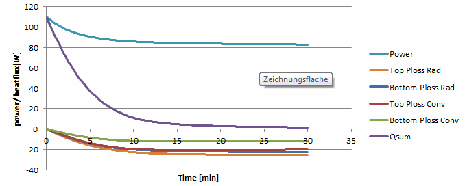
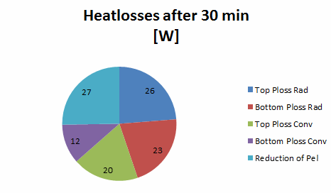
When the steady state is nearly reached the initial 110W of electric power are reduced to 0 by the following contributions (for a heat bed without insulation). It can be seen that a large portion of the heat is radiated by infrared radiation. This should possible to easily reduced by a factor of 8 to 9 by applying a aluminium foil (emissivity 0.11) beneath the heat-bed or insulation.
Analysis with the simulator
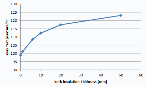
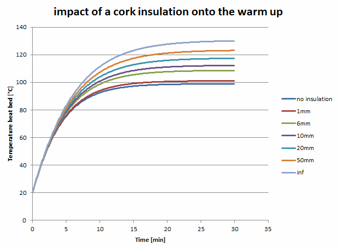
It can be seen with these curves that quite thick insulation is necessary for a large effect on the heat curve.
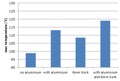
Nearly half of the of the heat is lost by infrared radiation. Therefore aluminum foil on the bottom is more effective than 6mm of cork. To reduce the heat-loss even more, combine them.
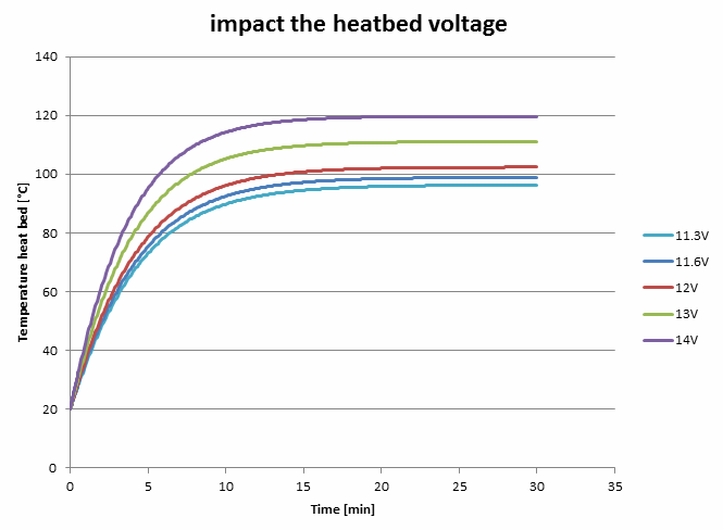
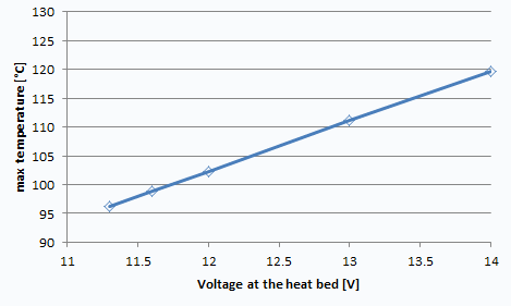
It can be seen with these curves that increasing the voltage on the heat-bed increases the speed and max temperature. This can be achieved by 3 measures:
- Use thicker wires between heat-bed and the board, and board and power supply (see the optimization chapter below).
- Solder wires directly onto the heat-bed (some soldering practice is needed).
- Increase the voltage of the power supply. This might be risky and is only recommended if you have replaced the original connectors. The power supply might exceed its limits, therefore a power supply with 30A at least is recommended by some users if 14V is used. Theoretically the Arduino in the Anet board can go up to 18V but only 12V is recommended for Arduinos. So it should be possible, but it is your own risk!
Some research on the Net
The heat-bed for the A8 was increased to 220 x 220mm from the original Prussa i3 design (200 x 200mm). Apparently the power was not scaled accordingly.
Some recommendations say you need 0.6 W/cm² for a heat-bed. This should mean 290W for the A8 heat-bed, but the A8 is not even half that value (it's only 110W).
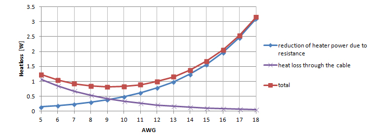
The optimal wire
The original wires from the A8 printer are thin; therefore their resistance leads to an power reduction to the heat-bed. If you use extremely thick wires you will create extra mechanical loads for the Y-axis stepper and, as cables are made of a very good thermal conductor, thicker wires will remove heat from your heat-bed via conduction. This rough estimation shows that AWG 9 would be an Optimum from the thermal point but the difference from an AWG 14 is minimal and AWG 14 is considerably more flexible and can be crimped with blue pre-insulated crimps. Also the extra 1 Watt of power saved by using AWG16 wire would only increase the max heat-bed temperature by 0.5K. I recommend silicone wires with many thin strands as they are much more flexible.
