Table of Contents
How to install the z-couplers (the right way)
Why should I do that?
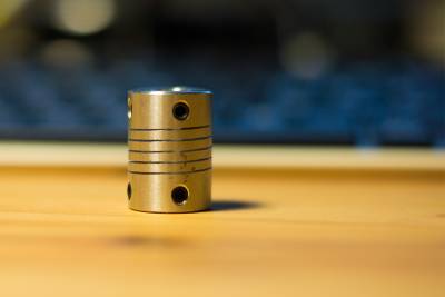
Couplers connect the motor to the threaded rods that move your z-axis up and down. If the motor and the rod are not perfectly aligned, the rotation of the motor will apply force to the rod and push it into x and y direction. This leads to the so called z-wobble and slightly shifted layers.
The correct installation
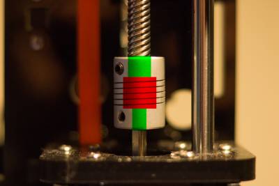
It's simple: The middle of the coupler must be flexible. So don't insert the rods until they touch each other, just insert the rods on both sides 5mm. They have to go just past the screws, but they don't need go in all the way.
A simple illustration:
The green marks show how deep the rods should sit in the coupler. The red mark shows where they should not go. ;)
Tighten your coupler
Remember to tighten the screws on the coupler in a cross-wise pattern. An example would be:
| 1 (first screw) | 3 (third screw) | |||
| 4 (last screw) | 2 (second screw) | |||
But my axis still wobbles!
There are many reasons for unwanted movements. Take a look at the troubleshooting, print some frame stabilizations and tighten your belts.
Be aware of all the so-called anti z-wobble devices found - especially those that constrain the threaded rod at the top of the printer. Securing the top of the rod makes the rod statically indeterminate, basically meaning that you over constrain the system. This will not help reduce z-wobble.
True anti z-wobble devices decouple x and y movement from z movement and/or take the spring movement out of the coupler by constraining the threaded rod at the bottom, above the coupler.

